The kind of hole to
be tapped has much to do with the style of tap that’s best suited. Some holes
go all the way through. Others, while not throughholes, still are relatively
deep. Some are quite shallow, little deeper than diameter. Each of these three
kinds of holes through, deep-bottoming blind, and shallow bottoming, has a tap
or group of taps best suited to requirements.
Taper
Taps have
7 to 10 thread chamfers to distribute cutting action over many teeth and the
taper also acts as a guide in starting.
Plug
Taps,
with a chamfer over four threads, is most widely used in through holes and
where there is sufficient room at the bottom in blind holes.
Bottoming
Taps are
made with just enough chamfer for starting in the hole, only 1 to 2 half
threads. As the name implies, it is designed to thread blind holes to the
bottom.
Tap Sizes have been
standardized to conform with those of standard screws, bolts, and studs.
Machine Screw tap sizes range from No. 0 through No. 14; No. 0 being
.0600" outside diameter; No. 1, .0730"; No. 2, .0860, etc.--all in
.0130 increments. Hand Taps, more commonly designated as Fractional Taps and
used today on all production machines, are designated in fractional and
integral inch sizes from 1/4" upwards.
Threads per Inch are shown for various tooth forms: the Unified series
adopted by Great Britain and the United States during the war, and the
corresponding American National Standard. NC and UNC mean coarse thread. NF and
UNF mean fine thread. NS means special thread.
Pitch Diameter is the basic dimension of a screw, threaded hole, or a
tap the diameter of an imaginary cylinder, the surface of which passes through
the thread where width of thread and space between threads are identical. This
cylinder, of course, would be a cone for tapered taps. It is upon Pitch
Diameter that tolerance limits are based to establish Class of Thread.
Class Of Thread
There are three
established Classes of Thread, designated in the Unified series by adding “A”
for screws and “B” for nuts (or other internal threads) to show definite limits
and tolerances.
Class 1B Thread is that in which a 1 A screw can be run in readily for
quick and easy assembly. The hole is classified as 1 B. The fit is 1 B Thread,
and rarely used in modern metalworking.
Class
2B
Thread consists of a 2A screw in a 2B hole. This 2B Thread has wide
application, accommodates plating, finishes, and coating to a limited extent
and, therefore, has fair tolerance allowances.
Class 3B Thread means a 3A Screw in a 3B Nut or threaded hole for
applications where tolerance limits are close.
In the tables that
follow, tap selections are shown for the Class of Thread desired and, under the
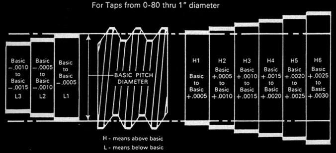
Class of Thread heading, applicable GH Numbers are listed. "G” designates
Ground Thread. “H” means that pitch diameter is on the high side of basic.
These two letters are followed by a numeral showing the tolerance of pitch
diameter oversize as follows:
H1 = Basic to Plus 0.0005"
H2 = Basic Plus 0.0005" to Plus 0.0010"
H3 = Basic Plus 0.0010" to Plus 0.0015"
H4 = Basic Plus 0.0015" to Plus 0.0020"
H5 = Basic Plus 0.0020" to Plus 0.0025"
H6 = Basic Plus 0.0025" to Plus 0.0030"
H7 = Basic Plus 0.0030" to Plus 0.0035"
The diagram below, exaggerated for clarity, illustrates these several selectives in Pitch Diameter tolerance--including "L" (undersize tolerance), although no "L" taps are shown in this book. Pitch Diameter varies with the number of threads per inch because the number of threads of Pitch of screw determines the height of thread. Since Basic Pitch Diameter is measured from points half the height of the fully formed thread, a hole drilled to provide theoretical 50% thread engagement would be of the same diameter as the pitch diameter of the tap.
The Basic Point In Thread Measurement
All
measurements must have a controlling point or base from which to start. In the
case of a screw thread, this control point is called the BASIC or theoretically
correct size, which is calculated on the basis of a full form thread. Thus, on
a given screw thread, we have the Basic Major Diameter, the Basic Pitch
Diameter and Basic Minor Diameter.
While it is impossible in practice to form screw threads to their precise
theoretical or BASIC Sizes, it is possible and practical to establish limits
which the deviation must not exceed. These are called the “Maximum” and
“Minimum” Limits. If the product is no smaller than the “Minimum Limit” and no
larger than the “Maximum Limit,” then it is within the size limits required.
This difference between the Maximum and Minimum Limits is the TOLERANCE.
In actual practice the Basic Size is not necessarily between the Maximum and
Minimum Limits. In most cases, the Basic Size is one of the Limits. In general,
tolerances for internal threads will be above Basic and for external threads,
below Basic. See drawing below.
For
graphic representation, the Basic Pitch Diameter is commonly designated by a
line with variations from it indicated by shorter lines spaced to represent a
numerical scale, as shown on the left half of the drawing below.
On an actual screw thread, the Basic Dimensions would follow the contour of the
theoretically perfect thread, as on the right half of the drawing below.
To find the basic pitch diameter or basic minor diameter of any screw thread,
subtract the constant for the number of threads per inch from the basic major
diameter.
For graphic representation, the Basic Pitch Diameter is commonly
designated by a line with variations from it indicated by shorter lines spaced
to represent a numerical scale, as shown on the left half of the drawing below.
On an actual screw thread, the Basic Dimensions would follow the contour of the
theoretically perfect thread, as on the right half of the drawing below.
To find the basic pitch diameter or basic minor diameter of any screw thread,
subtract the constant for the number of threads per inch from the basic major
diameter.
|
Constants For Finding Pitch Diameter And Minor Diameter Of Screw Threads |
|||||||
|
Constants for Finding |
Constants for Finding |
||||||
|
|
|
|
|||||
|
Threads Per |
|
|
|
|
|
|
|
|
80 |
0.012500 |
0.00812 |
0.00800 |
0.01083 |
0.01624 |
0.01601 |
0.02165 |
Thread Constants For Various Percentages
Formula
for Obtaining Tap Drill Sizes
(Select nearest commercial stock drill)
(Outside Diameter of Thread) - (0.01299 X Amount of Percentage of Full Thread /
Number of Threads per Inch) =
Drilled Hole Size
(Number of Threads per Inch) X (Outside Diameter of Thread - Selected Drill
Diameter / 0.01299) =
Percentage of Full Thread
Figures in table show amount to subtract from O.D. of screw to obtain specific
percentages of thread.
|
Threads Per |
|
|
|
|
|
|
|
|
6 |
0.21651 |
0.1300 |
0.1408 |
0.1517 |
0.1625 |
0.1733 |
0.1842 |
Relation Of Tap Pitch Diameter To Basic Pitch
Diameter
American tap manufacturers use a series of tap pitch diameter limits. These limits feature a .0005” tolerance in tap sizes #0 through 1 inch, and a .001 inch or greater tolerance in tap sizes above 1 inch through 1-1/2 inch diameter, inclusive. The chart shows the relationship between tap pitch diameter limits and basic (nominal) pitch diameter.
Tap Limits Product Limits And Class Of Thread
Engineers
frequently receive a request for a Class 3B (or other class) tap. Many times,
too, the customer will ask for a tap to produce a “Class 3B Fit”. Ordering taps
by these specifications is incorrect, and often impractical. The following
information is presented to clarify the difference between the terms Class of
Thread, Tap Limits and Product Limits to make ordering taps easier and aid the
customer in obtaining the tap best suited for his requirements.
Class of Thread refers simply to the tolerances that control the
closeness of fit between two threaded mating parts. This term should be used
only in reference to a threaded assembly, as, for example, a screw and nut.
Product Limits refers to the limits and tolerances of the internal
or female thread. The° of tolerance is expressed by the terms Class 2, 2B, 3
and 3B. Product limits refer to the various limits and tolerances applying to
nuts or internal threads and are identified by the terms Class 2, 2B, 3 or 3B.
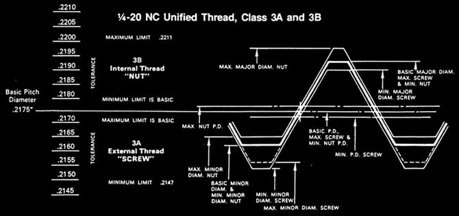
Tap Limits refers to the various sizes of taps manufactured to
permit selection of a tap which will produce an internal thread within the
desired product limit. Tap limits are designated as L-i, H-1 H-2, H-3, etc.
In the chart on this page we have illustrated the difference between tap and
product limit, using a 1/4-20 tapped hole as the example.
Although ground thread taps are produced to precision tolerances under closely
controlled manufacturing processes and are guaranteed for accuracy of
individual elements, there is always the possibility of the presence of unknown
factors which can be detrimental to good tap performance. The tap manufacturer,
therefore, is not able to guarantee the size of the tapped hole.
To summarize, the following points should be remembered:
1. A tap cannot produce a Class of Thread. It can produce a tapped hole within
specific product limits.
2. Since it is used only in tapping a hole, or producing an internal thread, a
tap has no control over the fitting properties of the mating external thread.
3. To produce what is commonly referred to as a “Class of Thread,” both the
external and internal threads must be within their respective product limits. Only
when both members of a threaded assembly fall within the desired class limits
can the proper fit be assured.
4. The acceptability of any class of threaded hole is determined only by an
accurate “Go” or “Hi” thread plug gage of the corresponding class. Similarly,
the acceptability of a male part with an external thread is also determined by
a corresponding “Go” or “Lo” thread ring gage.
5. When ordering taps, specify either the tap limit or the class of thread that
identifies the limit of the tapped hole.
6. In special applications, supply as much information as possible. The more
information our engineers have to work with, the better they can recommend a
tap to do the job properly with least expense.
7. Remember, it is not always the most expensive tap which will do the job
best. Our files contain many examples of special jobs which were solved with
inexpensive standard taps.